EMF Equation of a transformer
The emf equation of a transformer is derived by considering a single-phase transformer. When a single-phase AC supply is given to a transformer, the emf gets induced in the secondary winding by means of electromagnetic induction.
Let,
N1 be the number of turns in the primary winding.
N2 be the number of turns in the secondary winding.
ϕm be the maximum flux in core in webers.
f be the frequency of AC input voltage in Hertz.
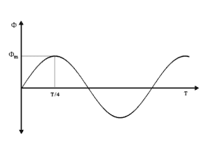
As shown in fig, flux ϕm increases from zero value to maximum value in one-quarter of the cycle, i.e., in 1/4f second.
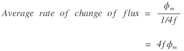
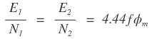
By faraday’s law of electromagnetic induction, rate of change of flux is nothing but induced emf,

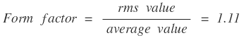
If the flux varies sinusoidally, then the rms value of induced emf is obtained by multiplying the average value with form factor.

The rms value of induced emf in the primary winding is given by,


Similarly, rms value of induced emf in the secondary winding is given by,

The above two equations are the emf equation of a transformer in the primary and secondary winding respectively.
From equations (1) and (2), we get the emf induced per turn in the primary and secondary winding of a transformer.
Dividing the equations (1) by (2), we get,
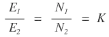
where K is a constant, called transformation ratio.
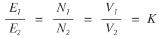
For an ideal transformer, E1 = V1 & E2 = V2
where
V1 – AC Supply voltage of transformer in the primary side.
V2 – Terminal voltage of transformer in the secondary side.
Thus, the transformation ratio K of a transformer is
In the above equation,
If N2 > N1 & E2 > E1 then the transformer is a step up transformer.
If N1 > N2 & E1 > E2 then the transformer is a step down transformer.


