Phase Difference in AC Circuits
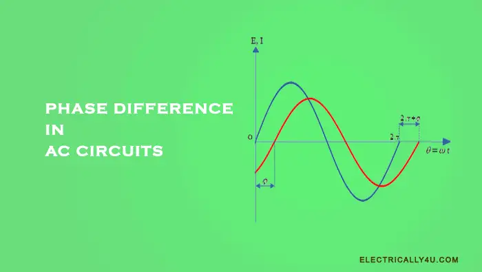
In the analysis of AC circuits, it is very difficult to deal with sinusoidal waveforms and their mathematical equations. It becomes a bit more difficult when dealing with two sinusoidal waveforms. Hence, phasor representation is an easier way to represent and analyze an alternating quantity.
What is phasor representation?
The phasor is a rotating vector quantity that has both magnitude and direction. It is graphically represented by means of a straight line with an arrow at one end, where the straight line represents the magnitude and the arrow represents the direction.
Phasor is the representation of a sinusoidal waveform at any instant of time, so phasors can be thought of as a function of time.
Consider a phasor rotating in an anticlockwise direction starting at position ‘a’ as shown in the below figure. If the projections of this phasor are plotted on the Y-axis(Voltage) against different angular intervals in time along the X-axis, we get a sinusoidal waveform.
The X-axis of the waveform represents the angle(θ = ωt) either in degrees or radians through which the phasor has moved. The angle through which the phasor has moved is called the phase angle.
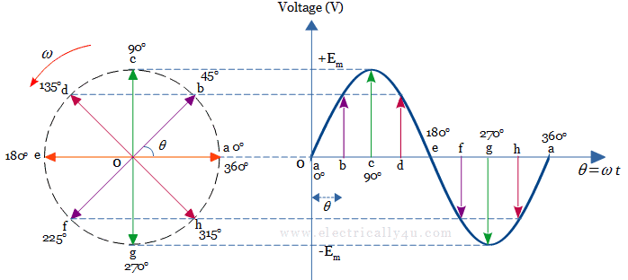
In this sinusoidal waveform, each position at the horizontal axis represents the elapsed time starting at time, t = 0. When the phasor is horizontal, its tip at position ‘a’ and ‘e’ represent the zero value at angles (0o, 360o) and 180o.
Similarly, when the phasor is vertical, its tip at position ‘c’ and ‘g’ represent the positive peak value(+Em) at 90o and the negative peak value (-Em) at 270o respectively. By this way, the phasor completes one full rotation.
One complete cycle of a sinusoidal AC waveform is represented by one complete rotation of a phasor with an angular velocity of ω = 2πƒ, where ƒ is the frequency of the waveform.
Phase Difference in ac circuits
Let us consider two sinusoidal waveforms having the same frequency ƒ Hz but are assumed to have different maximum values.
If one waveform starts at time t = 0 with a corresponding phase angle and another waveform starts to the left or to the right of this zero point, then there exists a difference in phase, called phase difference ϕ or phase shift of the waveform.
The phase difference is given by a general expression
![]()
Where
Amax is the amplitude of the sinusoidal waveform.
ωt is the angular frequency of the waveform in radian/sec.
ϕ is the phase angle in degrees or radians through which the second waveform has shifted either left or right from the reference point.
Let us learn the phase difference in AC circuits under three cases.
In-phase
Consider two alternating quantities, voltage and current having the same frequency ƒ Hz. As the frequency is the same, the angular velocity ω must also be the same.
Both the waveforms reach the maximum(+Em, +Im) and minimum(-Em, -Im) at the same time, also reaches the zero value at the same time. So at any instant in time we can say that the phase of voltage will be the same as the phase of the current.
The instantaneous value of voltage and current is given by,
![]()
![]()
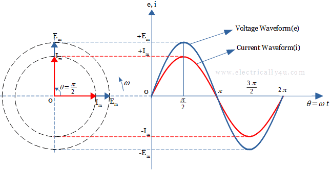
Thus the angle of rotation at any time will always be the same and the phase difference between the two quantities, i.e., e and i will therefore be zero(ϕ = 0).
As the frequency of the current and voltage are the same, they both reach their maximum, zero and minimum values at the same time, the two alternating quantities are said to be “in-phase”. Their amplitudes may be different but there exists no phase shift between them.
Lagging Phase Difference
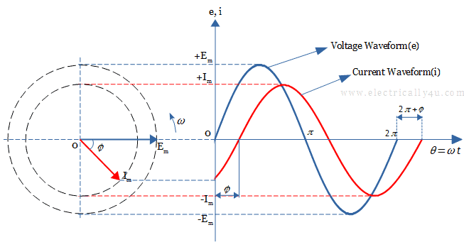
In this case, consider a voltage sine wave that starts at zero value along the horizontal axis, but at the same instant of time, the current sine wave has a negative value.
The current phasor achieves its zero value, maximum peak after the corresponding voltage phasor. Thus there exists a Phase difference between the two waveforms in an ac circuit.
As the two phasors are rotating in anticlockwise direction, the current falls back with respect to the voltage phasor, by an angle ϕ. This is called a lagging phase difference.
The voltage and current equations are given by,
![]()
![]()
In the above current equation, ωt – ϕ indicates that the current waveform(i) lags behind the voltage(e) by an angle ϕ in an inductive circuit.
Leading Phase Difference
Similarly, consider a voltage waveform that starts at zero value, but the current waveform has a positive value at that instant. It reaches its maximum peak and zero value, ϕ angle before the voltage waveform.
When the current phasor rotates ahead of the voltage phasor by an angle ϕ, the current waveform is said to be leading with respect to the voltage. This called a leading phase difference.
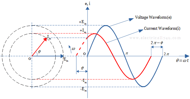
The voltage and current equations are given by,
![]()
![]()
In the above equation, ωt + ϕ indicates that the current waveform(i) leads the voltage(e) by an angle ϕ in a capacitive circuit.


