Transformer on load condition

A transformer is said to be on load when the primary is connected to the alternating voltage source and its secondary is connected to the load. When a transformer is operated at no load condition, the current from the secondary winding to the load will not flow.
But when the transformer is connected to the load, the secondary current flows from the winding to the load. Let us now look at what happens, when the load is connected to the transformer.
Operation of Transformer on load condition
When the secondary circuit of a transformer is connected through an impedance or load, the transformer is said to be loaded. The current I2 is set up in the secondary winding that flows through the load.
The magnitude and phase of this secondary current I2 with respect to secondary terminal voltage V₂ will depend upon the characteristics of the load, i.e., resistive, inductive, and capacitive.
If the load is resistive, the current I2 will be in-phase with V2. Similarly the current will lag behind and lead the terminal voltage if the load is inductive and capacitive respectively.
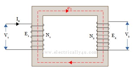
When the transformer is on no load, as shown in the above figure, it draws no-load current I0, from the supply mains. The no-load current I0 sets up an MMF (N1I0), which produces flux Φ0 in the core.
When an impedance is connected across the secondary terminals, as shown in the Figure below, current I2 flows through the secondary winding. The secondary current I2 sets up its own MMF(N2I2) and hence creates a secondary flux Φ2.
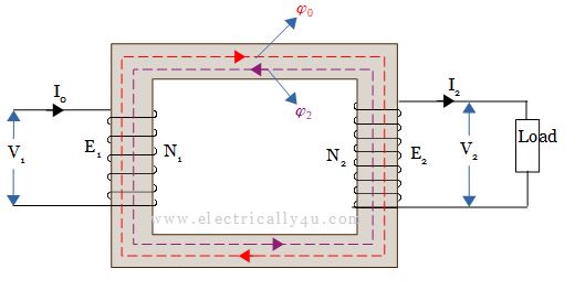
The secondary flux Φ₂ opposes the main flux set up by the exciting current I0, according to Lenz’s law. The opposing secondary flux Φ2 weakens the main flux momentarily, so primary back emf E1 tends to be reduced.
At this period, the applied voltage V1 will be more than the back emf E1. Thus the primary winding draws more current from the supply. It again causes an increase in back emf E1, and it adjusts itself such that there is a balance between applied voltage V₁ and back emf E₁.
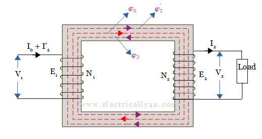
Let the additional primary current be I’2, called as load component of the primary current. The current I’2 is in phase opposition with secondary current I2 and is also called the counter-balancing current.
The additional current I’2 in the primary winding sets up an MMF (N1I’2) producing flux Φ’2 in the same direction as that of the main flux Φ0. It cancels the flux Φ₂ produced by secondary MMF (N₂I2) being equal in magnitude.
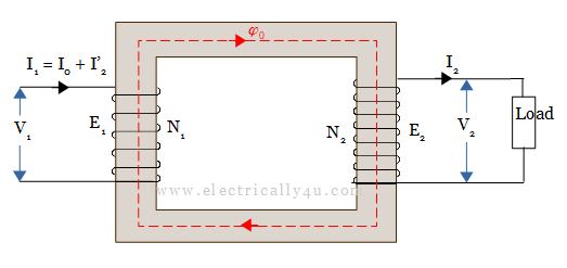
Hence during the load condition, only the main flux exists in the transformer core. Therefore, whatever might be the load condition, the flux passing through the core is almost constant as that of no load condition.
As Φ₂ = Φ’2
![]()
![]()
When the transformer is on load, the primary winding has two currents.
- No load current I0
- Counterbalancing or load component of primary current I’2
Thus the total primary current I1 is the phasor sum of both currents I0 and I’2.
![]()
Since the no-load current is very small compared to I’2, the total primary current is approximately equal to I’2
![]()
![]()
where K is called the transformation ratio.
From equation(2), it can be understood that the primary and secondary currents are inversely proportional to their respective turns.
Phasor diagram of a transformer on load
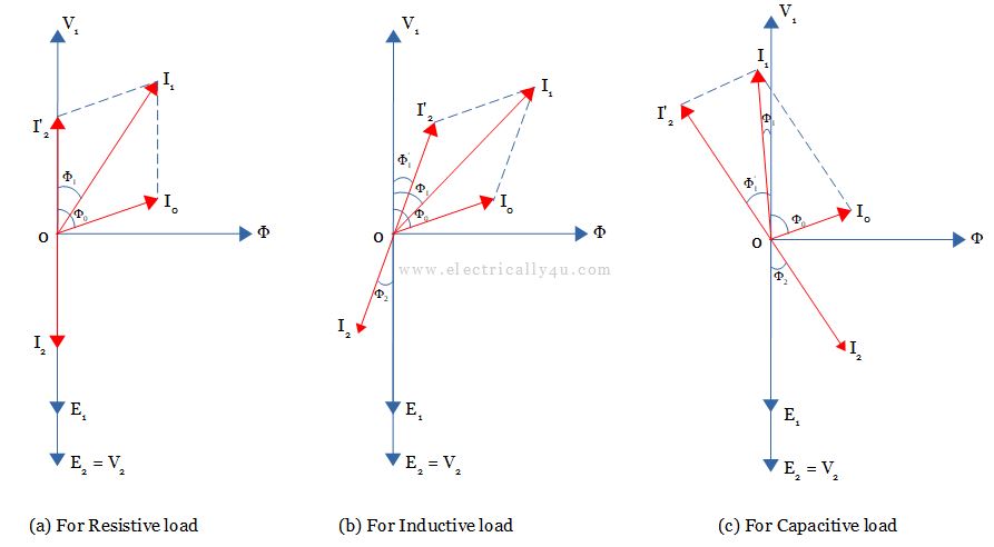
The phasor diagram of a transformer on load is drawn below for resistive, inductive, and capacitive loads. To draw the phasor diagram,
- Let us consider the flux Φ0 as the reference phasor.
- Draw the V1 phasor leading the flux Φ0 by 900.
- Draw the induced EMFs E1 and E2 phasor opposite to the voltage phasor V1.
- Draw the no-load primary current I0 by lagging V1 by an angle Φ0.
- Draw the secondary current I2.
- For different load conditions,
- Resistive Load – I2 is drawn in phase with V2.
- Inductive Load – I2 is drawn lagging V2 by an angle Φ2.
- Capacitive Load – I2 is drawn leading V2 by an angle Φ2.
- Draw the load component of primary current I’2, opposite and equal to the current phasor I2.
- Draw the primary current I1 lagging the voltage phasor V1 by an angle Φ1. I1 is also the vector sum of I0 and I’2.
