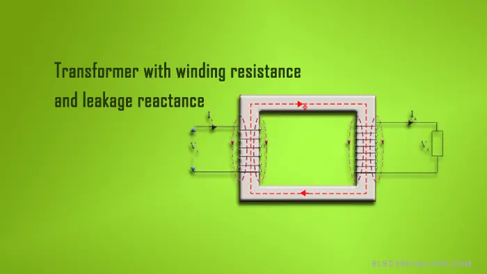
Transformer with winding resistance and leakage reactance

Resistance of transformer
An ideal transformer has no losses because it possesses no resistance. It is not possible to build an ideal transformer. But an actual transformer always has some resistance in the primary and secondary windings. Due to this resistance, there is some voltage drop in the two windings.
The result is that the EMF induced in the primary winding E1 is less than the primary input voltage. It is because of the resistance R1 in the primary winding. The equation becomes
![]()
The secondary terminal voltage V₂ is vectorially less than the secondary induced e.m.f. E2 because of the resistance R2 of the secondary winding. Hence, V2 becomes
![]()
Leakage Flux in transformer
For an ideal transformer, it was assumed that the entire flux developed by the primary winding, links with every turn of both the primary and secondary windings. But in practice, it is not possible to realize this condition.
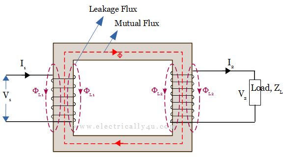
However, part of the flux ΦL1 set up by the primary winding links only with the primary turns, as illustrated in the figure below. Also, some of the flux ΦL2 set up by the secondary winding links only the secondary turns.

These two fluxes ΦL1 and ΦL2 are known as leakage flux. It is defined as the flux that leaks out of the core and does not link both windings.
The primary leakage flux ΦL1 is proportional to the primary current and the number of primary turns being fixed.
Leakage Reactance of transformer
On no load, the primary current is so small that the leakage flux produced by it can be neglected. Under load conditions, primary current increases resulting in an increase in ampere-turns, and hence leakage flux increases.
The primary leakage flux ΦL1 is in phase with I1 and produces self-induced emf EL1 given by EL1=2πfL1I1 in the primary winding, where L1 is the self-inductance of the primary winding produced by primary leakage flux ΦL1.
The self-induced emf EL1 due to primary leakage flux in the primary winding will lag the leakage flux ΦL1 and primary current I1 by 90°. This emf is nothing but the reactance voltage and is denoted by I1X1.
The effect of the primary leakage flux, therefore, is to induce an emf that opposes the flow of current through the transformer. The reactance of the primary winding X1 is written below as.
![]()
Similarly, when the transformer is operated on load, secondary current I2 flows through the secondary winding, which produces its own flux Φ2. A part of this flux will leak out of the core, called secondary leakage flux ΦL2, which is in phase with the secondary current I2.
This leakage flux produces self-induced emf EL2 = 2πfL2I2 in the secondary winding where L2 is self-inductance of secondary winding due to leakage flux ΦL2.
This emf is also called a reactance voltage I2X2 which lags the secondary current I2 by 90º, where X2 is the secondary reactance and is given as,
![]()
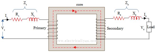
A transformer with winding resistance and leakage reactance is equivalent to an ideal transformer having inductive and resistive coils connected in series with each winding as shown below.

Impedance of Transformer
As discussed above, both primary and secondary windings will have resistance and leakage reactance. The combination of both resistance and reactance is nothing but the impedance of the transformer. If R1 and R2 are primary and secondary resistances, X1 and X2 are leakage reactances of the transformer respectively, then Z1 and Z2 are the impedance of primary and secondary windings. The equations of impedances are given by,
![]()
![]()


