Working principle of DC motor
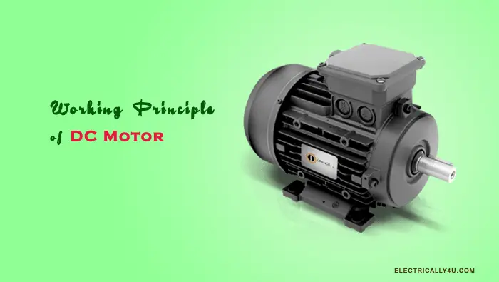
DC motor is an electrical machine that converts electrical energy into mechanical energy. The working principle of DC motor is given by, “When a current-carrying conductor is placed in a magnetic field, the conductor experiences a force which tends to the conductor”.
The direction of the rotation of the motor is given by Fleming’s Left-hand Rule and its magnitude of a mechanical force is given by F = BIL Newton.
Construction of DC Motor
Construction-wise, there is no difference between DC Generator and DC motor. In fact, a DC machine can be interchangeably used as a generator or as a motor.
The most important parts of the DC motor are the rotor and the stator. The rotor has the armature winding and the stator holds the field winding.
The parts of a DC motor are
- Magnetic frame or yoke
- Pole core and pole shoe
- Field coil or winding
- Armature core and winding
- Commutator
- Brushes
- Bearings and shaft
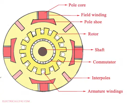
Based on the arrangement of field winding and the armature winding, there are different types of dc motors such as separately excited dc motor, shunt wound DC motor, DC series motor and compound type DC motor.
For a detailed study, Learn the construction of DC machines.
Working Principle of DC Motor
Have you wondered, how a dc motor works when you turn on the supply?
To understand the working principle of DC motor, let us consider the following figure. The figure shows a part of a multipolar DC motor. It has two field poles: the North(N) pole and the South(S) pole. The rotor is drawn as a semi-circle, which carries the armature conductor(shown as small circles).
When the dc motor is connected to the DC supply, the direct current flows through the brushes and commutator to the armature winding. Once the current passes through the commutator, it becomes alternating.
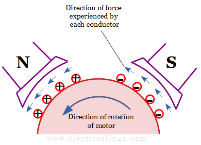
The armature conductors under the North pole carry the current in an inward direction(shown as a plus). Similarly, the conductors under the south pole carry current in an outward direction(shown as minus). Hence the group of conductors under the successive filed poles carry current in opposite direction.
Now each conductor under the respective poles experiences a force in a direction given by Fleming’s left-hand rule.
Fleming’s Left-Hand Rule
The Flemings’ left-hand rule states that “Stretch out the forefinger, middle finger and thumb of your left hand in such a way that they are mutually perpendicular to each other. If the forefinger represents the direction of the field(B) and the middle finger represents that of the current(I), then the thumb gives the direction of the force(F)”.
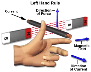
As per the above rule, when a current-carrying conductor is placed in a magnetic field perpendicularly, it experiences a mechanical force in a direction that is mutually perpendicular to both the field and the current-carrying conductor.
The arrow shown above each conductor denotes the direction of the force experienced by it. These forces collectively produce a rotating torque, which will rotate the dc motor.
The magnitude of the mechanical force is given by
F = BIl Newton —-> (1)
In this equation, B represents the magnetic flux density, I is the current flowing through the armature winding and l is the length of the conductor within the magnetic field.
When DC supply is connected to the armature winding, the current starts flowing through the DC motor. The magnetic field is produced by the field winding. As per equation(1), the mechanical force of rotation experienced by the armature conductors depends on the current, magnetic field, and length of the conductor.
Thus the conversion of electrical energy into mechanical energy is done during the operation of a DC motor.
Back Emf
As soon as the armature conductors start rotating, it cuts the magnetic field. So a dynamically induced emf is induced in the armature conductors according to Faraday’s Law of Electromagnetic Induction. The emf thus produced is said to be back emf or counter emf.
The direction of this induced emf is such that it opposes the armature current, which is given by Lenz’s law.
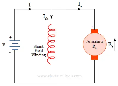
TThe above diagram represents the circuit of a DC motor, in which Eb denotes the back emf and the up arrow denotes the direction of induced emf.
The value of this induced back emf is equal to the emf induced in a dc generator, which is given by
![]()
where Φ is the magnetic flux produced,
N is the speed of the rotor in revolutions per minute,
Z is the total number of conductors,
P is the total number of poles and
A is the number of parallel paths.
TheThe applied voltage must force the current through the armature conductors against the back emf Eb.
Thus the mechanical energy produced is the result of armature current overcoming the dynamically induced emf.
Importance of Back Emf
The equivalent circuit of a DC motor is shown in the figure below. The armature circuit consists of armature resistance Ra, back emf Eb and brush contact drop Vbr. It is connected across a DC supply of V volts.
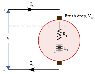
From the circuit, it can be observed that the applied voltage should be large enough to overcome the drops in armature resistance, brush contact and the back emf at all times. It is given by,
![]()
Where V is the applied voltage, Eb is the developed back emf, Ia is the armature current, Ra is the armature resistance, Vbr is the brush contact drop.
As the brush contact drop is very small, it can be neglected. Hence, the above equation can be re-written as,
![]()
From equation(1), it can be observed that the induced back emf(Eb) depends on the armature speed(N). Similarly from equation(2), it is observed that the armature current(Ia) depends on the back emf(Eb) for a constant applied voltage and armature resistance.
Considering both equations, we can say that when the armature speed is high, the back emf will be large and therefore the armature current is small. If the speed is low, then the back emf is less, which results in high value of armature current. Hence, high torque is produced.
Thus the presence of back emf makes the DC motor to act like a governor or a self-regulating machine.


