Armature winding in alternator

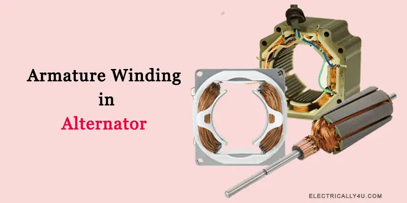
For an alternator, the armature is kept stationary on the stator. The stationary armature has several advantages over rotating armature. The armature winding is placed on the slots of the stator.
The armature winding of dc machine is of closed-circuit type. In the case of the alternator, it is either closed giving delta connection or open giving star connection. But, the general principles governing the armature winding of dc machine and alternator are the same.
Classification of Armature Winding
The different classification of armature winding is shown in the below figure.

Single phase armature winding
There are two types of single phase armature winding,
- Concentrated winding
- Distributed winding
Concentrated winding
If all the coil sides of any one phase under one pole are placed in one slot, the winding obtained is known as concentrated winding. Such winding give maximum induced emfs for a given number of conductors but the waveform is not exactly of sinusoidal waveform.
‘Skeleton Wave winding’ is a winding, in which the number of conductors or coil sides is equal to the number of poles. It is a single layer winding, which requires considerable space for the end connection of the coils and thus it is rarely used in practice.
If the single turns is replaced by multi turn coils to get higher emfs, then the winding is called ‘half-coiled or hemitropic‘ winding. Since coils cover only one half of the armature periphery, it is known as half-coiled or hemitropic winding.
Distributed winding
If the conductors are placed in several slots under one pole, then the winding is known as distributed winding. The winding may be partially distributed or completely distributed, depending on the slots, which may be spread over only a portion of the surface or over the entire surface.
Distributed winding have certain advantages,
- Harmonic emfs are reduced and so the waveform is improved.
- Distorting harmonics can be eliminated.
- Armature reaction and armature reactance is reduced to a greater extent.
- Efficient cooling is possible for the armature winding due to the distribution of winding.
- Core is also better utilised as the slots are evenly spaced.
Lap winding
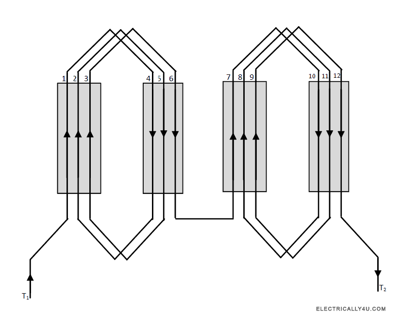
If the conductors are joined in such a way that their parallel paths and poles are equal in number, then it is a lap winding. i.e., A=P, where A is the number of parallel paths of a conductor and P is the number of poles.
Lap winding is employed in stator of high speed synchronous machine applications.
The below figure shown the structure of lap winding of a 4 pole, 12 slots, 12 conductor alternator.

Wave winding
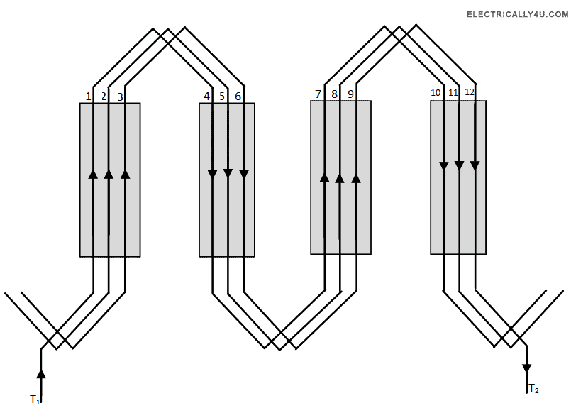
In wave winding, the number of parallel paths(A) is always equal to 2. The number of conductors per pole will be equal to the conductors in front end and back ends.
Wave windings are much suitable for the rotors of induction type motors.
The below figure shown the structure of wave winding of a 4 pole, 12 slots, 12 conductor alternator.

Concentric or spiral winding
In this winding, the coils are in spiral structure and they are of different pitches. Let us say, the outer coil pitch is 6, the middle coil pitch is 5 and the inner coil pitch is 4, etc.. They are widely used in slow speed applications.
Poly phase armature winding
Poly phase winding arrangements are similar to that of the single phase winding, the only difference is that, in two phase alternators there are two separate single phase winding placed 90 electrical degrees apart and in three phase winding, there are three separate winding placed 60 electrical degrees apart for convenience.
Balanced and unbalanced winding
If the number of coils per coil group is a whole number, then it is called balanced winding. Here, coil group is the product of number of phases and number of poles.
On the other hand, if the number of coils per coil group is not a whole number, then it is called unbalanced winding.
In unbalanced winding, the each pole contains unequal number of coils in different phases. But there should be equal number of coils in each phase.
Full pitch and short pitch winding
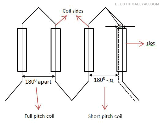
When the two coil sides forming a complete coil of a winding are 180 electrical degrees apart, the winding is called as full pitch winding.
When the coil span of the winding is less than 180 electrical degrees, i.e.,the two coil sides forming a complete coil of a winding are less than 180 electrical degrees apart, then the winding is known as short pitch winding or fractional pitch winding.
The below figure explains the full pitch and short pitch coil.

Integral slot and fractional slot winding
When the number of slots per pole per phase, m is an integer value, then the winding is called integral slot winding.
When the number of slots per pole per phase, m is an fractional number, then the winding is called fractional slot winding. This type of winding is little complicated but has certain advantage as well as ease in manufacturing.
However, in both cases, if the number of slots per phase must be a whole number, so that each phase will have the same number of coils.


