Electrical Power in AC circuits
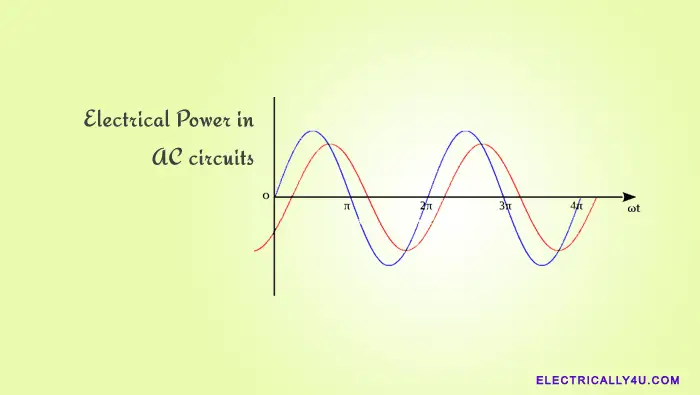
Electrical power is the rate at which the work is done or the rate at which the energy is being consumed in a circuit. Generally, all the electrical and electronic components have a specific power handling capacity. For example, a 20 watt LED light can handle power only up to 20 watts.
The electrical power consumed by an AC circuit is different from that of a DC circuit. In a DC circuit, the power is easily determined from the product of its voltage and current. It is because the DC voltage and DC current are constant with respect to time.
However, in an AC circuit, the total power is called apparent power. It is because, the voltage and current waveforms are sinusoidal, and so their amplitudes are constantly changing with respect to time. Thus the power is equal to the product of the RMS value of voltage(V) and the current(I) but it continuously varies with time.
The opposition to the current flow is called the resistance in the DC circuit. Whereas in an AC circuit, the opposition for the current flow is called the impedance. Impedance includes both resistance and reactance. So in addition to the power dissipated in resistance, the power components due to the reactances are also considered. Unlike a resistive component, the power in reactances is stored and then returned back to the supply.
Average value of Instantaneous power
The average power absorbed by a circuit is the algebraic sum of the dissipated power and the power returned to the source over one complete cycle. So a circuit’s average power consumption will be the average of the instantaneous power over one complete cycle. Since the sine function is periodic and continuous, the average power calculated over a single cycle is exactly the same as that for all time.
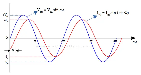
The instantaneous power is the power at any instant of time. It is given by the expression,
![]()
![]()
Thus the instantaneous power becomes,
![]()
Let ωt = θ. Now, the power becomes,
![]()
By applying the following trigonometry rule,
![]()
The power equation becomes,
![]()
The average power is obtained as,
![]()
![]()
![]()
Where V and I are the RMS values of the sinusoidal waveforms, v and i respectively. cos φ is the power factor and φ is the phase difference between the two waveforms. The resistor, inductor, and capacitor are the three passive components, which affect the phase difference between the two waveforms. Depending on the type of component used in a circuit, the power factor varies and so does the power.
AC Power in pure resistor
When a pure resistor is connected to an AC voltage source, the current through the circuit increases in proportion to the supply voltage. The voltage and current waveforms will be in-phase with each other. It means, the voltage and current waveforms travel on the same path. Both waveforms reach their peak and pass through zero at the same time.
The phase difference between the voltage and current waveforms is found to be 0o. The below figure shows the pure resistor circuit, its voltage waveform, current waveform, and phasor diagram of the pure resistor.
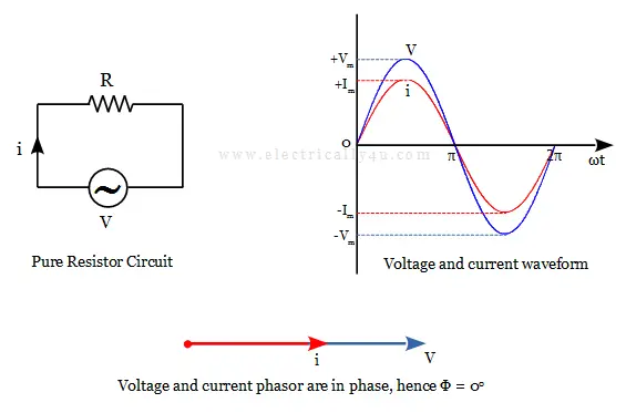
Tha average power in pure resistor is given as,
![]()
The power obtained above is called the Real Power(P) measured in watts(W). The resistor either consumes or dissipates the power. The amount of power dissipated depends on the amount of current flowing through the circuit.
AC Power in pure Inductor
In a pure inductor circuit, the voltage and current waveforms are not in-phase. When a changing voltage is applied to a purely inductive coil, back emf is induced in the coil due to its self-inductance. It will oppose the change in current flowing in the coil.
When a pure inductor is connected to a sinusoidal voltage supply, the current will lag behind the supply voltage by 900. In other words, the voltage phasor leads the current phasor by 900. Thus the phase difference between the voltage waveform and the current waveform is 90o leading.
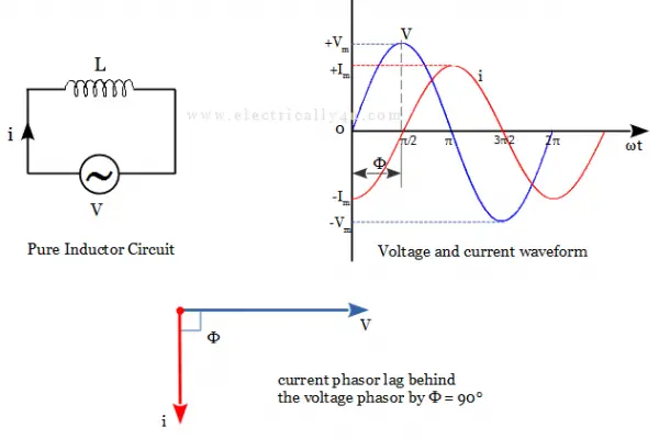
Tha average power in pure inductor is given as,
![]()
It is clearly seen that a pure inductor does not consume or dissipate any real power. The power in the case of an inductor is called Reactive Power(QL) measured in volt-amperes reactive(VAr). VAr represents the product of the voltage and amperes that are 90o out-of-phase with each other.
AC Power in pure Capacitor
A pure capacitive circuit has the property of delaying changes in the voltage across it. Capacitors have the ability to store electrical energy in the form of an electric field. It does not dissipate any energy but instead stores it.
When a pure capacitor is connected to a sinusoidal voltage, the current through the capacitor will lead the supply voltage by 900. It is because the voltage will not increase in phase with the current initially. The current flows through the capacitor and stores the charge.
It causes a delay for the voltage waveform to reach its peak value. The result is that the current always leads the voltage by 90o (π) in a pure capacitor circuit, as shown below. In other words, the voltage phase lag behind the current phasor by 900. It means the phase difference between the voltage waveform and the current waveform is 90o leading.
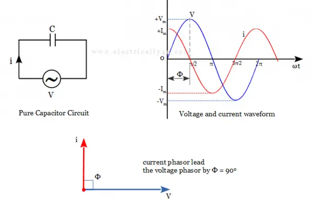
Tha average power in pure capacitor is given as,
![]()
Similar to the pure inductor circuit, the pure capacitor circuit does not consume or dissipate the real power. The charge gets stored in the capacitor plates and then returned back to the source. The power in this case is called reactive power(QC) measured in volt-amperes reactive(VAr).
Thus it is concluded that, in the resistor circuit, the power flows from the source to the component and is dissipated in the form of heat or light. Thus the average power is found to be the product of voltage and current. Whereas in inductor and capacitor circuits, the power flows to and fro between the source and the component. Hence the average power is found to be zero.

