Equivalent resistance and reactance of transformer

The transformer has two independent circuits primary and secondary winding. The two circuits can be resolved into an equivalent circuit to make the calculations simple.
Consider a practical transformer as shown below, which has primary and secondary windings whose resistance and reactances are R1 and R2 and X1 and X2 respectively.
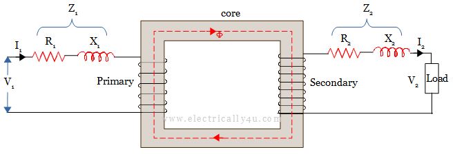
The voltage drops due to primary resistance and reactances are I1R1 and I1X1 respectively. Similarly, the voltage drops due to secondary resistance and reactances are I2R2 and I2X2 respectively.
The equivalent resistance and reactance of transformer is calculated by transferring the circuit parameters either from primary to secondary or from secondary to primary.
Equivalent resistance and reactance referred to Secondary
To make the calculations simple, let us transfer the circuit parameters(primary voltage, resistance, and reactances) from the primary side to the secondary side.
As you know, the transformation ratio is given by,
![]()
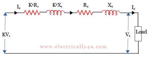
The voltage drops in the primary winding referred to secondary is K times, that is KV1. So the primary resistive and reactive drops referred to secondary can be written as KI1R1 and KI1X1 respectively. If I1 is replaced with KI2(from the transformation ratio), the drops due to primary resistance and reactance will become K2I2R1 and K2I2X1 respectively.
Total resistive drop in the transformer = K2I2R1 + I2R2 = I2(K2R1 + R2) = I2R02
Total reactive drop in the transformer = K2I2X1 + I2X2 = I2(K2X1 + X2) = I2X02
In the above equations, R02 and X02 represent the equivalent resistance and reactances of the primary winding referred to secondary. Now the above circuit can be redrawn as,
The phasor diagram for the obtained circuit is drawn below. Consider the terminal voltage as the reference phasor. Since the load is inductive, the secondary current I2 lags behind V2 by Φ. The drops due to resistance(I2R02) and reactances(I2X02) are drawn parallel and perpendicular to the current phasor. Join OC, the input voltage referred to secondary.
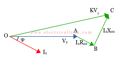
From the phasor diagram,
![]()
![]()
In this equation, the term (I2 X02 cosɸ – I2 R02 sinɸ) is very small compared to (V2 + I2R02 cosɸ + I2 X02 sinɸ). Hence neglecting the smaller term, we get,
![]()
![]()
![]()
For pure resistive load, Φ = 0, hence the equation(1) becomes,
![]()
For pure capacitive load, current I2 leads the voltage V2 by Φ and so it is taken as negative(-), hence the equation(1) becomes
![]()
Equivalent resistance and reactance referred to Primary
In the same way as before, the secondary winding parameters can be transferred to the primary to make the calculations simple.
With respect to the transformation ratio, the voltage drop due to secondary resistance and reactance referred to primary are ![]() and
and ![]() respectively. But from the transformation ratio,
respectively. But from the transformation ratio, ![]() . Thus the secondary resistive and reactive voltage drops referred to primary will become
. Thus the secondary resistive and reactive voltage drops referred to primary will become ![]() and
and ![]() respectively.
respectively.
Total resistive drop in the transformer =
![]()
Total reactive drop in the transformer =
![]()
In the above equations, R01 and X01 represent the equivalent resistance and reactances of the secondary winding referred to primary. Now the above circuit can be redrawn as,
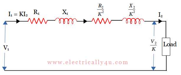
The phasor diagram for the above circuit is drawn below. Consider the terminal voltage V1 as the reference phasor. Since the load is inductive, the primary current I1 lags behind V1 by Φ. The drops due to resistance(I1R01) and reactances(I1X01) are drawn parallel and perpendicular to the current phasor. Join OC, the input voltage referred to primary.
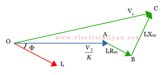
From the phasor diagram,
![]()
![]()
In this equation, the term ![]() is very small compared to
is very small compared to ![]() . Hence neglecting the smaller term, we get,
. Hence neglecting the smaller term, we get,
![]()
![]()
For pure resistive load, Φ = 0, hence the equation(3) becomes,
![]()
For pure capacitive load, current I2 leads the voltage V2 by Φ and so it is taken as negative(-), hence the equation(3) becomes
![]()
Solved Problem 1
A 20 kVA, 2000/200 V, 50 Hz, single-phase transformer has the following parameters: R1 = 1.25 Ω, R2 = 0.0025 Ω, X1 = 2.8 Ω, X2 = 0.0065 Ω. Calculate: (i) Equivalent resistance referred to primary and secondary. (ii) Equivalent reactance referred to primary and secondary.
Solution: Given data: R1 = 1.25 Ω, R2 = 0.0025 Ω, X1 = 2.8 Ω, X2 = 0.0065 Ω
Transformation ratio,
![]()
(i) Equivalent resistance referred to primary,
![]()
Equivalent resistance referred to secondary,
![]()
(ii) Equivalent reactance referred to primary,
![]()
Equivalent reactance referred to secondary,
![]()
Solved Problem 2
A 10 kVA, 2000/400 V, 50 Hz single-phase transformer at no load has R1=4.5 Ω, R2=0.3 Ω, X1=11 Ω, X2=0.50 Ω. Determine the approximate value of the secondary voltage at full load, 0.8 pf (lagging).
Solution: Given data: R1 = 4.5 Ω, R2 = 0.3 Ω, X1 = 11 Ω, X2 = 0.50 Ω
Transformation ratio,
![]()
Equivalent resistance referred to secondary,
![]()
Equivalent reactance referred to secondary,
![]()
At full load, secondary current is calculated from rated KVA
![]()
Secondary voltage,
![]()
![]()
![]()


