Norton’s Theorem with solved problem
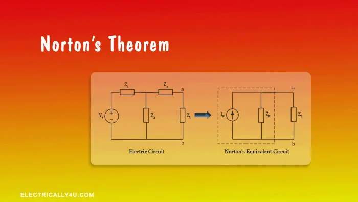
Norton’s theorem is used to solve complex circuits consisting of several sources and impedances by converting them into a simple equivalent circuit called Norton’s equivalent circuit. Now let’s look at the statement.
Norton’s Theorem states that
“Any linear bilateral circuit containing several energy sources and impedances can be replaced with an equivalent circuit consisting of single Norton’s current source in parallel with Norton’s impedance connected across the load impedance“.
Norton’s equivalent circuit has a single current source called Norton’s current source(IN), an equivalent impedance called Norton’s equivalent impedance ZN, and a load impedance ZL.
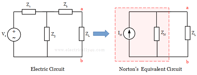
In the above equivalent circuit, Norton’s current IN is nothing but a short-circuit current, which is obtained by shorting the load impedance ZL.
Norton’s equivalent impedance ZN is obtained by the same procedure followed in Thevenin’s theorem. The equivalent impedance is obtained by short-circuiting all the voltage sources, open-circuiting all the current sources in the circuit, and removing the load resistor from the circuit.
Now, let us look at the step-by-step procedure to determine the IN and ZN in the above circuit.
Procedure to determine Norton’s equivalent circuit
Step 1 – Determination of Norton’s current
Remove the load impedance ZL in the given electric circuit and short it by joining the terminal ‘ab’ with a line as shown in the below figure.
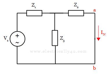
Now, in the following figure, we need to find the current IN that is flowing in the terminal ab. To find this current, it is necessary to determine the total current in the circuit. The total current IT can be determined by using Ohm’s law,
![]()
From the obtained value of total current IT, the current through the impedance Z2(or Norton’s current IN) is determined by using the current division rule.
![]()
Step 2 – Determination of Norton’s Impedance
Since there is only one voltage source available in the circuit, remove the voltage source, short the voltage terminals, and remove the load impedance, as shown in the figure below.
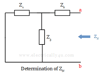
The Norton’s equivalent impedance is obtained from terminal ab using the formula,
![]()
Step 3 – Formation of Norton’s equivalent circuit
Using the obtained values of VN and ZN, the equivalent circuit is drawn below. This circuit is called Norton’s equivalent circuit.
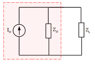
Now, from this circuit, the current through the load IL can be determined by using the current division rule. It is given by,
![]()
Solved Problem 1
For the given circuit, determine the current flowing through 10 Ω resistor using Norton’s theorem.
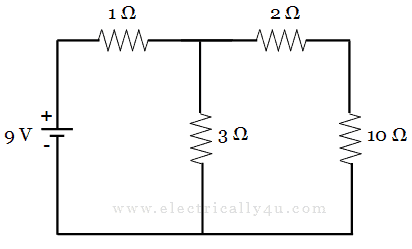
Since the question here, is to determine the current through 10 Ω resistor, it is considered as the load.
(a) To find Norton’s current, Remove the load resistor(10 Ω), short it with a wire and the circuit is redrawn as below.
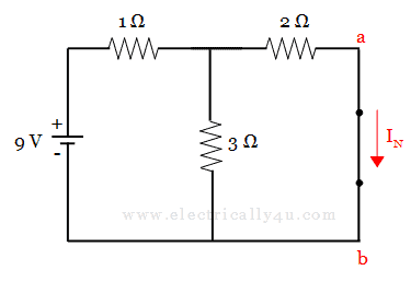
In this circuit, we need to find the current IN, which is Norton’s current flowing from a to b. To find the value of IN, it is necessary to determine the total current in the circuit.
If you observe the circuit, 3 Ω resistor and 2 Ω resistor are in parallel with each other. This parallel combination is in series with 1 Ω resistor. Thus,
![]()
Now, the total current IT is given by,
![]()
The current through the 2 Ω resistor (or Norton’s current IN) is obtained by applying the current division rule,
![]()
(b)To find Norton’s resistance, Remove the load resistor, short the voltage source and the circuit is redrawn as below.
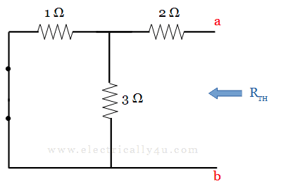
In this circuit, we can observe that the 2 Ω resistor is in series with the parallel combination of 1 Ω and 3 Ω resistors. Thus the equivalent value of resistance is obtained as,
![]()
[Learn how to find the equivalent resistance of resistor when they are connected in series and parallel.]
(c)Norton’s Equivalent Circuit. It is drawn by connecting Norton’s voltage IN, Norton’s resistance RN and load resistor in series, as shown below
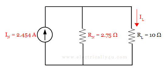
From this circuit, the current through the load RL = 10 Ω resistor is obtained using current division rule. It is given by,
![]()
Solved Problem 2
Determine the current through AB in the given circuit using Norton’s theorem.
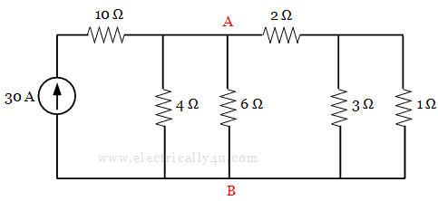
Since the question here is to find the current through AB, 6 Ω resistor is considered as the load.
(a) To find Norton’s current, Remove the load resistor(6 Ω), short it with a wire and the circuit is redrawn as below.
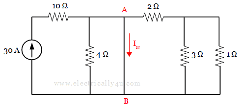
In this circuit, we need to find the current IN through path AB. Since path AB has low resistance, maximum current will flow through this path. Hence the circuit can be reduced and drawn as below,
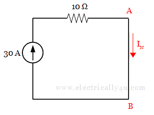
From this circuit, The current flowing through path AB, i.e., Norton’s current, IN = 30 A.
(b)To find Norton’s resistance, Remove the load resistor, open the current source and the resulting circuit is redrawn as below.
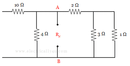
When you observe this circuit, there will not be any current flow through 10 Ω resistor, as it is open. Also, 3 Ω resistor and 1 Ω resistor are in parallel with each other, the combination of which is in series with 2 Ω resistor. The circuit can be redrawn as,
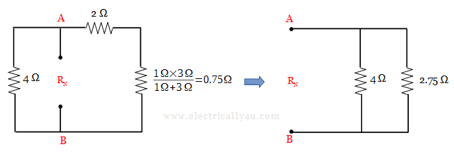
The Norton’s equivalent resistance can be obtained as,
![]()
(c)Norton’s Equivalent Circuit. It is drawn by connecting Norton’s voltage IN, Norton’s resistance RN and load resistor in series, as shown below
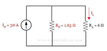
From this circuit, the current through the load RL = 6 Ω resistor is obtained using current division rule. It is given by,
![]()


Sir, But when we solved the first problem by Thevenin’s theorem we got the current through load resistance as 0.84 A but when we solved the same circuit with Norton’s theorem we got the current through load resistance as 0.52 A. Now I am confused, I think we should get same amount of current through load resistance. Please correct me and reply.
You will get the same amount of current through load resistance, when it is solved by using Thevenin’s theorem. I have solved the same problem using Thevenin’s theorem. Check this solved problem.