Superposition Theorem with solved problems
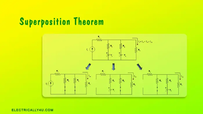
Superposition theorem is used to solve the complex electric network, which consists of two or more sources and several resistances, by considering and analyzing all the sources individually.
Superposition theorem states that,
“In any linear, bilateral network having more than one source, the response across any element is the sum of the responses obtained from each source considered separately and all other sources are replaced by their internal resistance.”
It can also be stated as,
If a linear circuit consists of more than one independent source, then the current flowing through any part of the circuit is equal to the algebraic sum of the currents produced by each independent source, when it is considered separately.
Illustration of Superposition theorem
Let us understand this theorem with the following circuit, which consists of three independent sources(I1, V1, V2), several resistances(R1, R2, R3) and a load resistor RL.
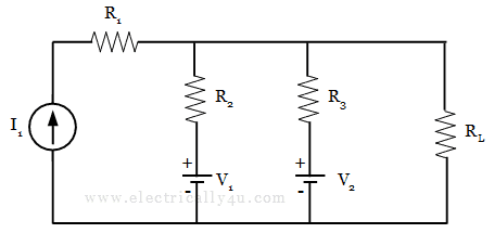
Now, to determine the current flowing through the load resistor RL, the circuit is analyzed by considering each source independently. While considering a single source, all other voltage sources in the circuit must be short-circuited and the current source, if any should be open-circuited.
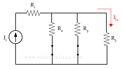
By considering the current source I1 alone acting in the circuit, as shown below, the current IL1 through the load is determined.
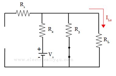
Now, this current source is open-circuited and the second source(Here, it is voltage source V1) is connected in the circuit, as shown below. Considering this voltage source V1 alone acting in the circuit, the current through the load IL2 is determined.
Similarly, the circuit is reconnected with the next voltage source V2, while the other voltage source is short-circuited and the current source is open-circuited. Considering this voltage source V2 alone acting in the circuit, the current through the load IL3 is determined.
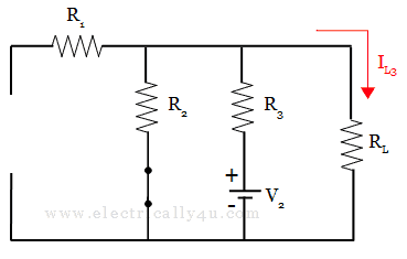
Now, according to the superposition theorem, the current flowing through any part of the circuit is equal to the algebraic sum of the currents produced by each independent source.
Thus the current flowing through the load RL is given by,
IL = IL1 + IL2 + IL3
Steps to solve the circuits using Superposition Theorem
- Identify the load resistor (RL) in the given problem.
- Considering a single source alone acting in the circuit, short-circuit the other voltage sources and open the current sources, if any.
- Calculate the current flowing through the load resistor RL due to a single source.
- Repeat steps 2 and 3 for all other sources in the circuit.
- To find the total current through the load resistor, perform an algebraic sum of the currents produced by each independent source.
Solved Problem 1
Find the current through 3 Ω resistor using superposition theorem.
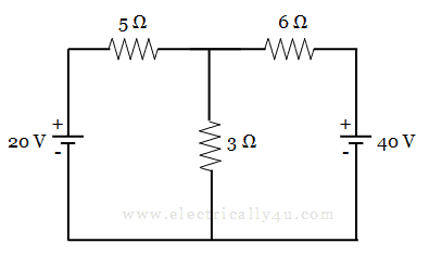
Let I1 and I2 are the currents flowing through the 3 Ω resistor, due to the voltage sources 20 v and 40 v respectively.
(i) To find I1.
Consider 20 v voltage source alone. Hence, Short circuit the other voltage source and the circuit is redrawn as below,
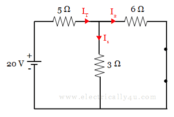
Now, to find the current through 3 Ω resistor, it is necessary to determine the total current supplied by the source (IT).
When you observe the circuit, 3 Ω and 6 Ω resistors are in parallel with each other. This parallel combination is connected in series with a 5 Ω resistor. Hence the equivalent or total resistance is obtained as below,
![]()
By applying Ohm’s law,
![]()
Now, the current through 3 Ω resistor is determined by using current division rule. It is given by,
![]()
(ii) To find I2.
Consider 40 v voltage source alone. Hence, Short circuit the other voltage source and the circuit is redrawn as below,
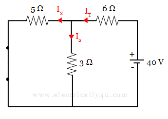
Now, to find the current through 3 Ω resistor, it is necessary to determine the total current supplied by the source (IT).
When you observe the circuit, 3 Ω and 5 Ω resistors are in parallel with each other. This parallel combination is connected in series with a 6 Ω resistor. Hence the equivalent or total resistance is obtained as below,
![]()
By applying Ohm’s law,
![]()
Now, the current through 3 Ω resistor is determined by using current division rule. It is given by,
![]()
The below figure shows the resultant circuit, which depicts the currents produced because of two voltage sources 20 v and 40 v acting individually.
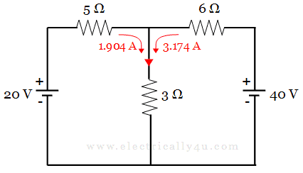
By superposition theorem, the total current is determined by adding the individual currents produced by 20 v and 40 v.
Thus the current through 3 Ω resistor is = I1 + I2 = 1.904 + 3.174 = 5.078 A
Solved Problem 2
Find the voltage across through 15 Ω resistor using superposition theorem.
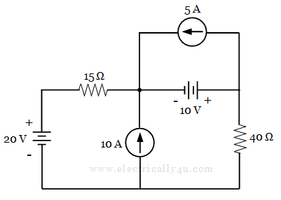
Let V1, V2, V3, V4 be the voltages across the 15 Ω resistor when each source (20v, 10v, 10A, 5A sources) are considered separately. Hence the resultant voltage is given by,
VT = V1 + V2 + V3 + V4
(i) To find V1
Consider 20v source alone. Hence the other two current sources are open-circuited and a voltage source is short-circuited. The circuit is redrawn as below,
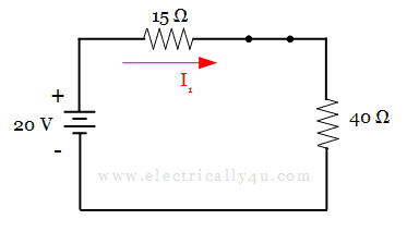
By applying KVL, the current through the 15 Ω resistor is given by,
![]()
Thus,the voltage across the 15 Ω resistor is given by,
![]()
(ii) To find V2
Consider 10v source alone. Hence the other two current sources are open-circuited and a voltage source is short-circuited. The circuit is redrawn as below,
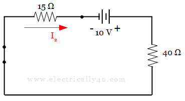
By applying KVL, the current through the 15 Ω resistor is given by,
![]()
Thus,the voltage across the 15 Ω resistor is given by,
![]()
(iii) To find V3
Consider 10A source alone. Hence the other two voltage sources are short-circuited and a current source is open-circuited. The circuit is redrawn as below,
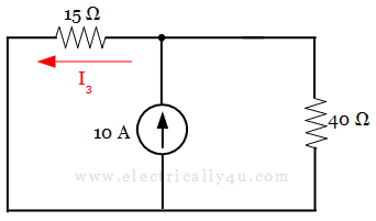
Here, 15 Ω and 40 Ω resistors in parallel with each other, hence by using current division rule, current through the 15 Ω resistor is given by,
![]()
Thus, the voltage across the 15 Ω resistor is given by,
![]()
(iv) To find V4
Consider 5A source alone. Hence the other two voltage sources are short-circuited and a current source is open-circuited. The circuit is redrawn as below,
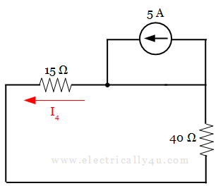
Here, since the circuit has a low resistance path, a negligible amount of current flows through 15 Ω resistor. Hence, current through the 15 Ω resistor is given by,
![]()
Thus, the voltage across the 15 Ω resistor is given by,
![]()
Therefore, by the superposition theorem, the resultant voltage is given,
![]()
In the above expression, the negative sign in V3 indicates that the direction of the current, in that case, is opposite to the assumed direction in the circuit.




Thank you very much, you have provided a concise and comprehensive explanation.
Hope you will solve more solutions
Solve problems on all theorems ?
Very good
In step iii,
Since we need current through 15 ohm resistor, shouldn’t it be:
I3= 10*15/(15+40) ?
No. that’s the wrong way. Since it is a parallel circuit, the current division rule is applied. Kindly go through the rule to get a clear idea.
very good notes.Easily understandable.Thank you
Glad to know that the contents are understandable. Thank you.
Sir actually i want to ask u a numerical question related to superposition theorem how i can sen u the question
You can post the question here or you can send it through the mail: info@electrically4u.com
Sir, in the second problem to actually verify superpositon theorem v total should also be calculated when all the sources are active which you didn’t mention there will you please explain the process involved there in detail?
The superposition theorem is used not to verify but to solve complex electric circuits. To verify this theorem, you can either simulate the circuit in any simulation software or you can do it practically.
In the superposition theorem, the current or voltage due to each individual source is determined and then they are added to find the resultant(total) current or voltage across the given load. The same is followed for both the problems.
kindly check the above steps to solve.
Am so glad because my problems in this area are now fully solved.
Receive m gratitude
for problem 2, step (iv) can you please explain how/where the low resistance path works and why the 15 ohm resistor has a negligible resistance.
thanks
in step (iv), for the 5A source, there are two paths for the flow of current. One path is through 15Ω resistance and the other path is the short-circuited path, which is across the current source.
In an electrical circuit, a short circuit will have very low resistance.
Since there is very low resistance in this path, all the current from the source rushes through the short circuit path, making a negligible amount of current to flow through 15Ω resistance.
That is the reason, I4 =0.
And in your question, you have asked, “why the 15 ohm resistor has a negligible resistance.”
15Ω resistor will never have negligible resistance. It has its own resistance of 15Ω.
In part iv, to find for V4, you said the other current source is open-circuited but on the re-drawing of the circuit it is short-circuited.
Yeah, you are right. It was corrected now and thanks for showing the mistake.
I don’t also understand why v4 in problem 2 is completely zero.
I try using Ohms law for it, it was 0.060v.
Can you help explain to me more better.
Could you please tell me how you applied Ohm’s law?
I don’t know how I can easily understand part iv, the reason for completely ignoring 5A, does it mean it’s not contributing any voltage to resistor 15, if it does then why not considering it.
Secondly, I am asking, in part iii, when we connect to 10A, resistors 15 and 40 are considered to be in parallel, what about when on IV, when connected to 5A, are they in parallel or series?