Real power, Reactive power, and Apparent Power | Power Triangle
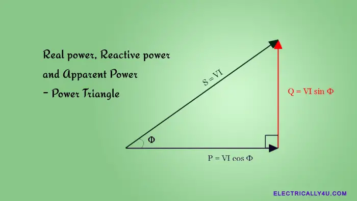
In an AC circuit, the total power consumed is called the apparent power. The power triangle is the representation of a right-angle triangle showing the relation between active power, reactive power, and apparent power.
Almost all electrical loads operate on alternating current(AC). Each load has its own resistance. Furthermore, some loads have inductive reactance, some have capacitive reactances while some have both inductive and capacitive reactances. The resistance and reactances are collectively called impedance, but it is not an algebraic sum of both.
Impedance is the vector sum of the resistance and reactance, that has a magnitude(Z) and a phase angle(Φ). The total impedance of the load determines how much active and reactive power it consumes. The concepts of active, reactive, and apparent power can be difficult to grasp. The information provided below can assist you in comprehending them.
Real Power
Real power is the power consumed by the resistive part of a circuit. It is the same as that of the power in the DC circuit. Real power performs the real work in an electrical circuit. It is also known as true power or active power or useful power. Real power is measured in terms of watts(W) and is denoted by P.
A circuit with only resistances does not produce any phasor difference between voltage and current waveforms(Φ = 0). All the power delivered to the resistance is dissipated in the form of heat, light, or some work.
Lamp loads and electric heaters are examples of resistive loads. Thus the power consumed by resistance is a real power which is fundamentally the circuit’s average power.
It is always calculated as
![]()
where R is the total resistive component of the circuit. V and I are the RMS values of voltage and current respectively.
Reactive Power
Reactive power does not perform any useful work in a circuit. It is the power that flows between the source and the load. Reactive power is associated with reactive elements such as inductors and capacitors.
The inductors consume the reactive power whereas the capacitors generate reactive power. Hence both the elements stores and return back the power to the source without consuming the real power. It is also called imaginary power or wattless power. It produces a phase shift between the voltage and current waveforms.
Reactive power is always calculated as
![]()
where X is the total reactive component(reactance) of the circuit. In a pure reactance circuit, the voltage and current phasor are 900 out of phase with each other. Hence the reactive power becomes,
![]()
The reactive power represents the product of volts and amperes that are out-of-phase with each other by an angle Φ.
Apparent Power
In AC circuits, the power delivered to the load comprises two components as discussed above. One is the real power(P) dissipated by the resistance and the other is the reactive power(P) supplied to the reactance.
As a result, the voltage and current waveforms do not have the same path. But there exists a phase shift between them.
Real power and reactive power can be represented in a complex form and are hence called complex power. It is given as,
![]()
![]()
In the above equation, the real part(P) denotes the real power and the imaginary part(Q) denotes the reactive power. It is not the algebraic sum of the real and reactive powers, but is the vector sum of P and Q. Its unit is expressed in volt-amperes.
The absolute value of the complex power is called apparent power. It is given as,
![]()
Apparent power is the total power or the demand in an AC circuit. The product of the RMS value of AC voltage(V) and that of the current(I) flowing through the circuit is called the apparent power. Its unit is given as volt-ampere and represented by the symbol S.
Apparent power is calculated as,
![]()
Power Triangle
Similar to the impedance triangle, the real power, reactive power, and apparent power are trigonometrically related with the help of a right-angle triangle. It shows the vector sum of real and reactive power in the form of a power triangle, as shown below.
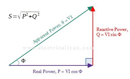
In the above figure, the real, reactive, and apparent power make up the sides of a triangle respectively. The adjacent side represents the real power, the opposite side represents the reactive power and the hypotenuse represents the apparent power. Φ is the phase angle made by the real power and apparent power.
If the phase angle is more, it means the circuit consumes more reactive power. For example, if phase angle Φ is 00, the power factor value, cos Φ = 1, implies that the purely resistive load is connected to the circuit.
For a phase angle of 250, the power factor cos Φ becomes 0.906, the circuit is more resistive and less reactive. If the Φ value is 750, the power factor becomes 0.258, the circuit is more reactive and less resistive.
Finally, if the phase angle becomes 900, the power factor will become cos Φ = 0, which implies that a purely reactive load(inductive) is connected to the circuit.
From the power triangle, the following calculations can be done,
![]()
![]()
![]()
![]()
![]()
![]()
From the power triangle, it is understood that at a power factor of cos Φ, an AC circuit requires a total power of S kVA to produce a useful work of P kW.
Power Factor
In an AC circuit, the power factor plays a vital role. It is the factor that decides the amount of real power flowing in the circuit. The power factor is the cosine of the angle between the voltage and the current waveforms.
It is defined as the ratio of the real power absorbed by the load to the apparent power flowing in the circuit. Its value lies between 0 and 1 and has no unit.
Power factor is given by the formula,
![]()
![]()
The power factor can also be determined from the ratio of resistance and impedance.
![]()
Solved Problem
An inductor coil having a resistance of 10 Ω and inductance of 50 mH is connected to a 220 V, 50 Hz supply. Calculate the current, real power, reactive power, and apparent power. Draw the power triangle.
Given. V = 220 V, f = 50 Hz, R = 10 Ω, L = 50 mH
Solution.
To find the total impedance in the circuit, let us determine the inductive reeactance. It is given as,
![]()
![]()
Current through the coil is,
![]()
Power factor is given as,
![]()
![]()
Real power or active power is given as,
![]()
Reactive power is given as,
![]()
Apparent Power is the given as,
![]()
The power triangle for the given problem is drawn as below,
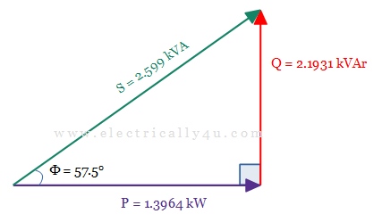
The power triangle above explains that at a power factor of 0.537, the inductor coil requires 2.599 kVA of power to produce 1.3964 kW of useful work.

