What is an Inductor?
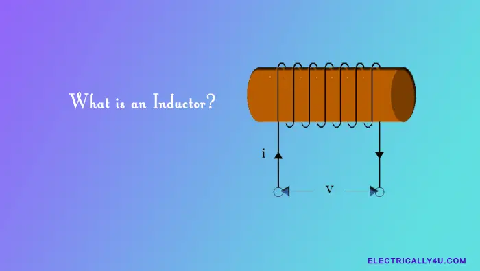
An inductor is a two-terminal passive electronic component that is capable of storing electrical energy in the form of a magnetic field when current flows through it. It is also called a coil, a choke, or a reactor.
An inductor typically consists of a coil of wire wound around the central core. The central core can be either a straight cylindrical rod or a continuous loop or ring rod to concentrate their magnetic flux. Constructing a coil of wire into an inductor produces a much stronger magnetic field.
Types and symbols of Inductor
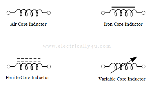
The schematic symbol for an inductor is as simple as a coil of wire. Hence a coil of wire can also be termed an Inductor. Inductors are typically classified based on the type of inner core wrapped around them.
The types of inductor are: hollow or air core, solid iron core, soft ferrite core, and variable core. Air core type inductor coil does not use a magnetic core made of a ferromagnetic material.
The different core types are denoted by adding continuous or dotted parallel lines above the coil, as shown below.
As said before, an inductor coil has a central core area(A) with a constant number of turns of wire(N) per unit length(l). It is shown in the below figure.
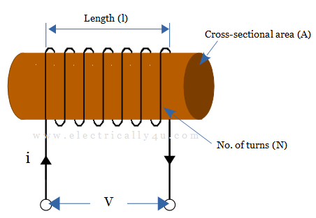
An inductor opposes the rate of change of current flowing through it due to the self-induced voltage. The induced voltage is proportional to the rate of change in current flow. The inductor produces a magnetic flux proportional to the amount of current i flowing through it. The induced magnetic flux is in the opposite direction to the flow of current.
Inductance
In simple words, inductors oppose the rate of change of current but will easily pass a steady-state DC current. This property is known as inductance(L). Its unit is Henry(H) named after Joseph Henry. The larger an inductor’s inductance, the greater the capacity to store electrical energy in the form of magnetic energy.
If the current i flows through a coil of N turns, it produces a magnetic field Φ and so the coil has a magnetic flux linkage of NΦ. According to Faraday’s Law, any change in the magnetic flux linkage produces a self-induced voltage in the coil, given by
![]()
A time-varying magnetic field induces a voltage proportional to the rate of change of the current producing it, with a positive value representing an increase in emf and a negative value representing a decrease in emf.
![]()
![]()
where L is the constant of proportionality called inductance. The inductance depends on the magnetic permeability of the core material (μ), the number of turns in the wire coil (N), the cross-sectional area of the coil (A), and the length of the coil (l). It is given by an expression,
![]()
The relation between the flux in the inductor and the current flowing through the inductor is given as, NΦ = Li. The inductance may be either self-inductance or mutual inductance. The equivalent inductance of the inductors connected in series and parallel will have different values.
How Do Inductors Work?
An inductor opposes the changes in current flow by inducing a voltage across it that is proportional to the rate of change in current flow. Consider the following circuit diagram below to understand how an inductor works in a circuit.
A lamp, a wire coil (inductor), and a switch are connected to a battery as shown. From the circuit, when the inductor is removed, the lamp illuminates normally. The circuit behaves in a different way when the inductor is connected.
When the switch is closed, the majority of the current starts to flow through the coil. It is because it provides a low-resistance path for the current. As a result, we anticipate that lamp to glow very dimly.
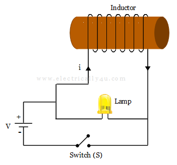
However, because of the inductor behavior in the circuit, when we close the switch, the lamp glows brightly and then gradually fades, and when we open the switch, the bulb glows brightly and then quickly goes out.
When a voltage or potential difference is applied across an inductor, the electric current flowing through it generates a magnetic field. According to Lenz’s law, this magnetic field induces an electric current in the inductor with the opposite polarity.
The induced current caused by the inductor’s magnetic field attempts to oppose any change, increase or decrease, in the current. The current can flow normally once the magnetic field is established.
When the switch is closed, the magnetic field around the inductor maintains current flow until the magnetic field collapses. Even though the switch is turned off, this current keep the lamp lit for a short period of time.
In other words, the inductor stores energy in the form of a magnetic field and resists changes in the current flowing through it. As a result, the current flowing through an inductor cannot change instantaneously.
Voltage and current across an Inductor
Consider a pure inductor electrical circuit as shown below. When the switch(S) is open, no current flows through the inductor. As no current flows through the inductor, the rate of change of current (di/dt) in the inductor coil will be zero. Hence, there is no self-induced back-emf(VL = 0) within the inductor.
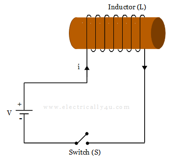
If the switch(S) is closed at time t = 0, a current starts to flow through the circuit. The current gradually increases to its maximum value at a rate determined by the inductance of the inductor. The rate of current flowing through the inductor multiplied by its inductance produces a self-induced emf across the coil given by Faraday’s equation,
![]()
where,
VL = Instantaneous voltage across the inductor in Volts,
L = Inductance in Henry,
di/dt = rate of change of current in ampere per second
This self-induced emf across the inductor coil(VL) opposes the applied voltage until the current reaches its maximum value and reaches a steady-state condition. Now, a constant DC current flows through the coil, thus the rate of change of current is zero at this instance.
Similarly, when the switch(S) is opened, the current flowing through the inductor decreases. But it opposes this change and attempts to maintain the current flowing at its previous value by inducing another voltage in the opposite direction. The voltage and current across the inductor are shown below.
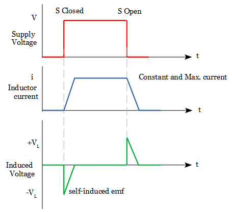
When the current is decreasing, the voltage polarity acts as a source, and when the current is increasing, the voltage polarity acts as a load. As a result, for the same rate of current change through the coil, the magnitude of the induced emf will be the same whether it is increased or decreased.
Power in an Inductor
As per Lenz’s Law, an inductor opposes the current flow through the circuit. It is because the flow of current induces an electromotive force (emf) that opposes it. In order to keep the current flowing against this induced emf, work has to be done by the external voltage source. The instantaneous power used in forcing the current against this self-induced emf is given below.
![]()
The power in a circuit is given by,
![Rendered by QuickLaTeX.com \[ P = vi = \Bigg[ L \frac{di}{dt} \Bigg] *i = \frac{1}{2} L \frac{di^2}{dt} = \frac{d}{dt} \Bigg[ \frac{1}{2} Li^2 \Bigg] \]](https://electrically4u.com/wp-content/ql-cache/quicklatex.com-1f624b1544968057ed1bcc327dddf2a8_l3.png)
An ideal inductor has no resistance but only has inductance. Thus there will be no power loss, which means no power is dissipated in the inductor coil.
Energy in an Inductor
When a current flows through the inductor, the magnetic field generated is nothing but the energy stored in the coil. If the current through the inductor coil increases and di/dt becomes greater than zero, the instantaneous power in the circuit must also be greater than zero. It means the energy is stored in the inductor.
In the similar way, when current through the inductor decreases, the magnetic field associated with it collapses. Thereby the stored energy in the inductor is returned back to the source. The equation of energy in an inductor is obtained by integrating the power equation where the total magnetic energy being stored in the inductor is always positive. It is given by,
![]()
Inductors are the passive electrical component as they store and deliver energy to the circuit, but they cannot generate energy. An ideal inductor is said to be a loss-less component which means no energy is lost. Hence it can store the energy indefinitely.


