RL Series circuit
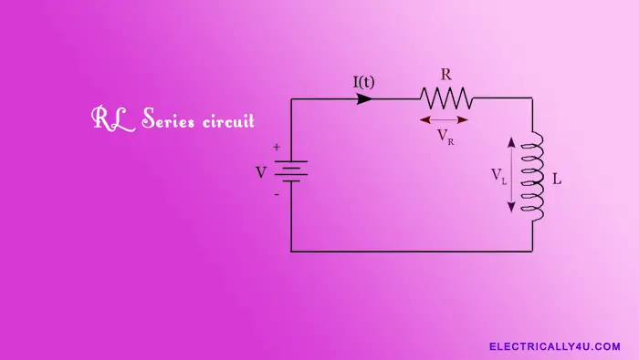
An RL series circuit consists of passive circuit elements such as an inductor and resistance connected together to a source. In an electrical circuit, an inductor opposes the rate of change of current through the coil, but a resistance opposes the flow of current through the coil.
In the previous article, we analyzed the inductor without considering the resistance. A pure inductor will have no resistance. But in the real time, when an inductor is used, there exists a resistance in the coil. It is because, the inductor coil uses copper wire, which has its own resistance.
Thus in real-world analysis, we can consider the simple coil as being an inductance(L) in series with a resistance(R). Together, they form an LR Series Circuit or RL series circuit.
Working of RL Series circuit
An RL Series circuit consists of an inductor having an inductance, L connected in series with a resistor having a resistance, R, as shown below. The RL series circuit is connected to a constant voltage source or battery.
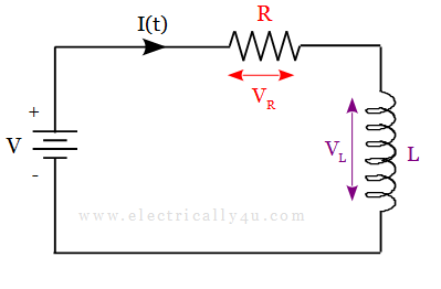
Since it is a series circuit, the current flowing through the circuit is the same, i.e., I = IR = IL. The current through the circuit starts to flow but does not rise rapidly to its maximum value of Imax as per the Ohm’s Law (I=V/R). It is because of the self-induced emf in the inductor.
After some time, the voltage source neutralizes the effect of the self-induced emf. Hence, the current flow becomes constant and the induced current and field are reduced to zero.
By applying Kirchhoff’s Voltage Law, it is possible to find the total voltage drop that exists in the circuit. It is given as,
![]()
The voltage drop across an inductor is given as,
![]()
The voltage drop across the resistor is given as,
![]()
The expression for the total voltage drop in the circuit is given as,
![]()
From the above expression, we can observe that the voltage drop across the resistor depends upon the current I, while the voltage drop across the inductor depends upon the rate of change of the current di/dt.
Let us consider the initial inductor current is equal to zero and is excited by a DC voltage of V volts. When the switch is closed at time t = 0, we get the transient response. The above expressions(transient equations) can be rewritten as,
Current through RL circuit,
![]()
Voltage across a resistor,
![]()
Voltage across an inductor,
![]()
Where 𝜏 is the time constant of RL series circuit.
Time constant of RL series circuit
The time constant of an RL circuit is defined as the time taken by the current to reach its maximum steady-state value if the initial rate of rise is maintained. The time constant(𝜏) of a series RL circuit is the ratio of inductance(L) to that of resistance(R).
![]()
In an RL series circuit, the current in the circuit does not build up at a steady rate because of the inductor. It has the property to oppose the change in current flowing through the circuit. As a result, the rate of flow of current increases rapidly but slows as it approaches its maximum value. The below graph shows the transient response of the series RL circuit.
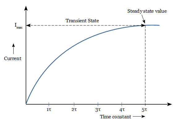
In order to reach 63.21 % of its final steady-state value, it takes 5-time constants to build up a current in the RL circuit. It means the charging time required for an RL circuit is 5*(L/R). It is the transient time of the circuit. At this time, the inductance in the inductor is reduced to zero and behaves like a short circuit.
The transient time of an RL circuit can be determined from the relationship between the inductance and the resistance. For example, consider the case of an RL circuit, which has fixed resistance and a larger inductance value. This circuit will have a slower transient time and therefore a longer time constant.
Likewise, for a constant inductance value, the smaller the resistance, the longer the transient time. As the resistance is increased, the circuit becomes more and more resistive. So the value of the inductance becomes negligible compared to the resistance. Hence the transient time and therefore the time constant of the circuit becomes shorter. Further increase in resistance, would effectively reduce the transient time to almost zero.
Power in an RL circuit
The power delivered to the circuit is given by,
![]()
The power is dissipated by the resistor is given by
![]()
The energy stored in the inductor in the form of magnetic energy or the power absorbed by the inductor is given as
![]()
Thus the total power in a RL series circuit is equal to the power dissipated by the resistor and the power absorbed by the inductor. It is given by
![]()
Solved Problem
An RL series circuit is excited by a DC supply of 20 V. Find the steady-state current, time constant, transient time and the induced voltage in the inductor after 10 ms. Take the resistance and inductance value as R = 4 Ω and L = 50 mH respectively.
Given. R = 4Ω, L = 50 mH, V = 20 V
Solution.
Steady state current, I = V/R = 20/4 = 5 A
Time constant, 𝜏 = L/R = 0.05/4 = 0.0125 s
Transient time = 5𝜏 = 5* 0.0125 = 0.0625 s
Induced emf is given by the formula,
![]()

